Located at Penitentiary
Glen
|
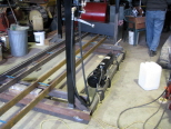
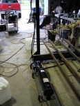
Went over to Dave Fosters to help with the lift and he had the hydraulic unit clamped into position with the hoses connected. View looking from the other direction of the hydraulic unit and the two sets of rails that are 13 feet long. |
||
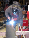
We clamped the four hinges to the cyclinder cover in preparation to welding them in place. Dave welding the hinge in place with three more to go. |
||
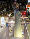
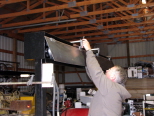
After hoisting the cover panel in place we clamped it to the sheet metal at the top to mark and drill the holes for the cover hinges so it will be removable if we need to do so. A view of the 30 inch throw cyclinder and the pulleys we used for the project. |
||
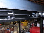
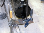
Looking straight into the cyclinder box at the top of the lift showing the layout we used. The bottom support of the lifting table was interferring with the base bracket so Dave marked it for cutting it off to clear. |
||
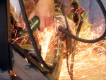
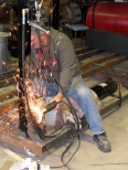
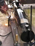
Using a cutoff wheel in a grinder to cut through the tubular steel created a dance of sparks. Because of the tight quarters Dave had to make some entry cuts to get the cutoff wheel close enough to the marked line for the finish cut. |
||
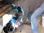
Welding the support plates for the hydraulic pump to the tubular frame of after we double checked the position to make sure the cover over the pump unit would be supported. The angle clips that the cover will bolt into are clamped into place and ready for welding. |
||
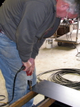
Welding the clip at the far end of the pump for the cover support with the angles set back 1/8" so the cover would be supported by the plate just not the bolt through the angle. After marking the pump cover when it was in place for the mounting holes Dave drilled the holes in the U formed cover. |
||
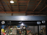
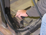
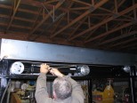
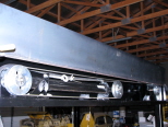
We started rigging the cables around the pulleys and to their tie points and put on the cable clamps. The cyclinder box showing the cables in place that they still need tensioning. |
||
| This site is copyright 2000-2018 |
|---|

